 Home
Projects
Publications
Home
Projects
Publications

Timeline: Started and completed early summer 2021
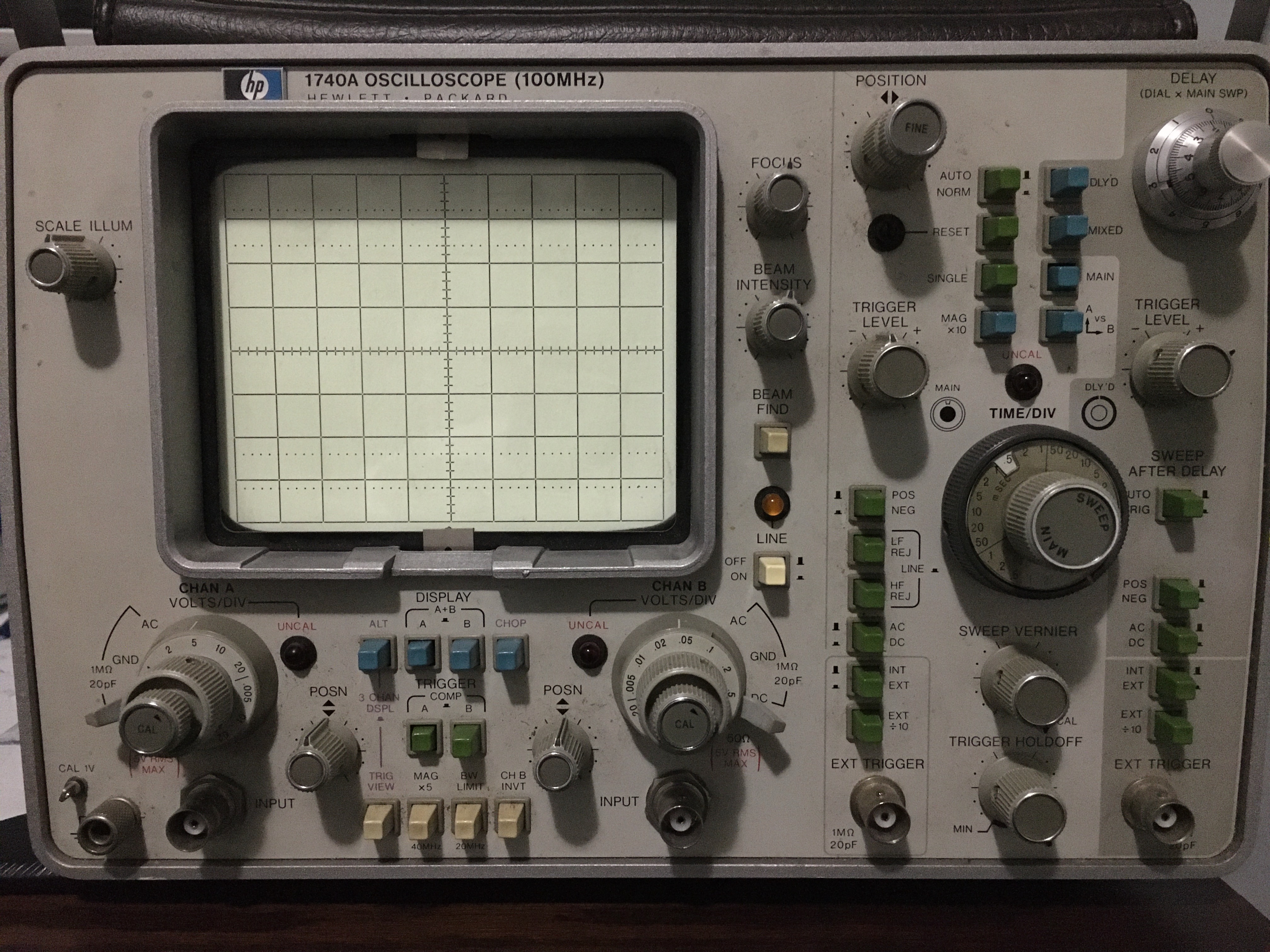
I bought an HP 1740A analog scilloscope off Kijiji for $60, which worked perfectly on channel A, but had no trace on channel B. It came with a service manual which included all the circuit diagrams and calibration procedures, and two HP 10006D 10x attenuation probes. I hoped to fix the channel and have a fully-working 2-channel oscilloscope. This was my first electronics project apart from small Arduino-type projects in early high school.
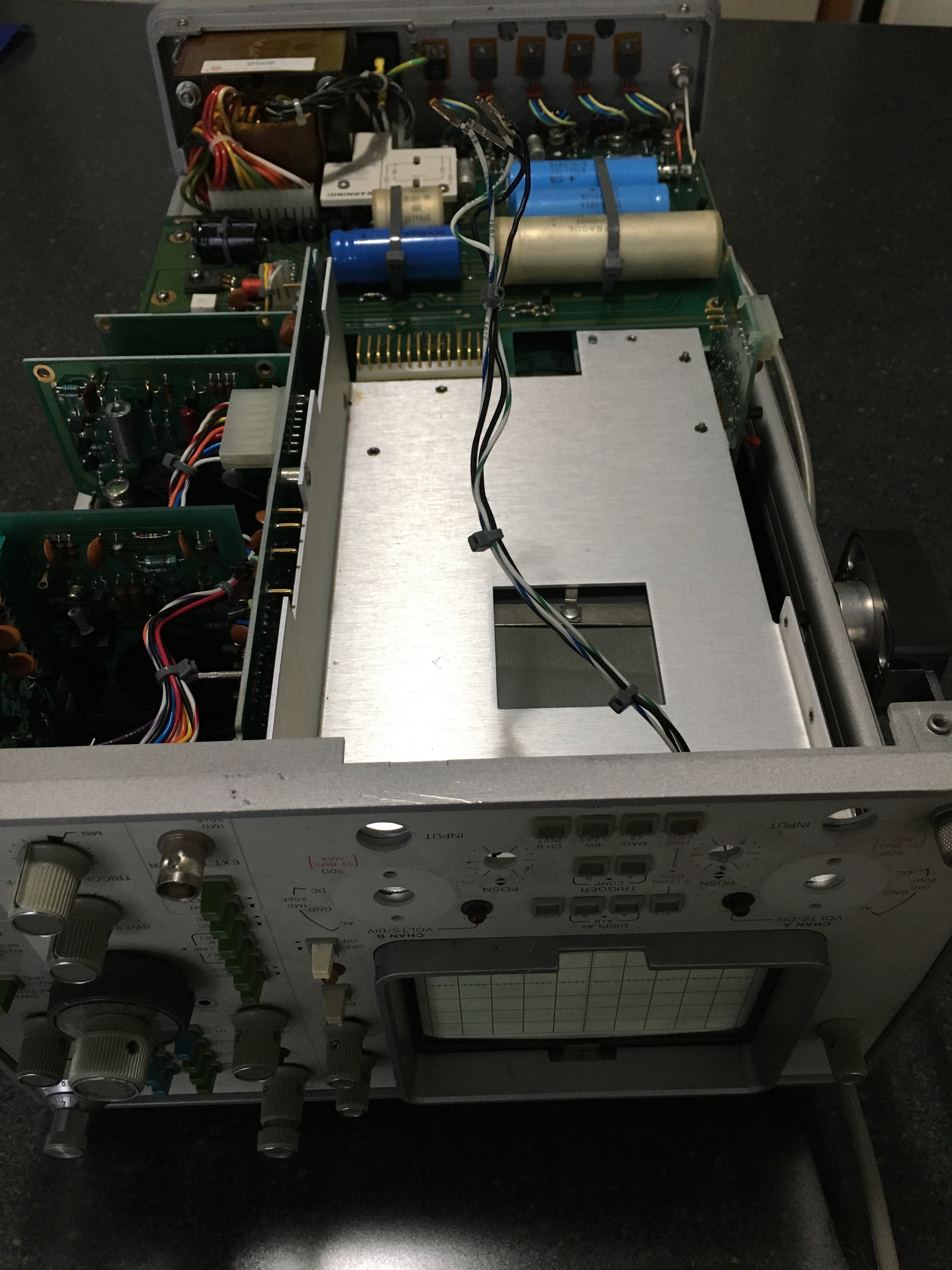
The plastic covers come off with a couple screws, and the PCBs are immediately visible, both on the top and the bottom.
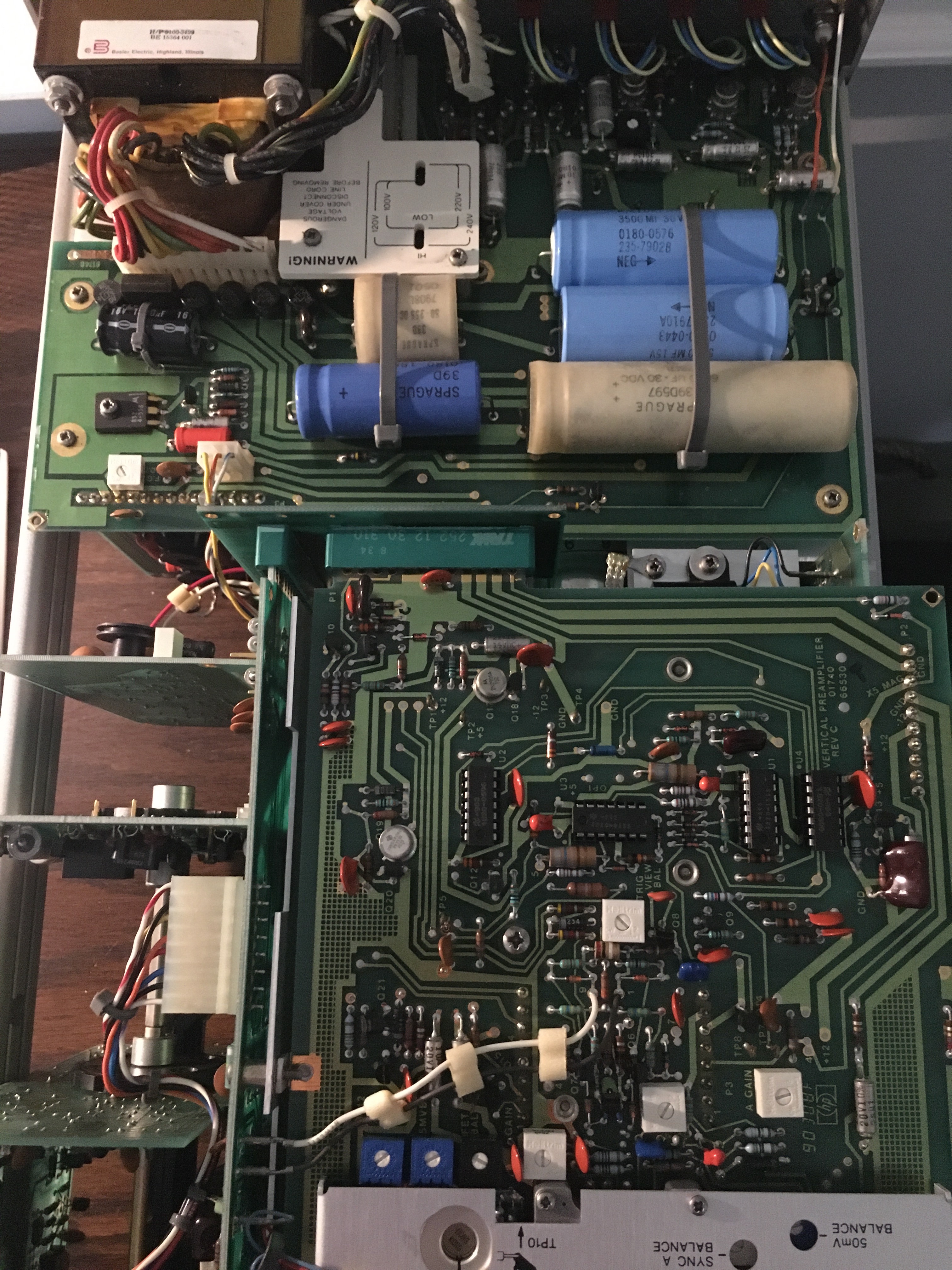
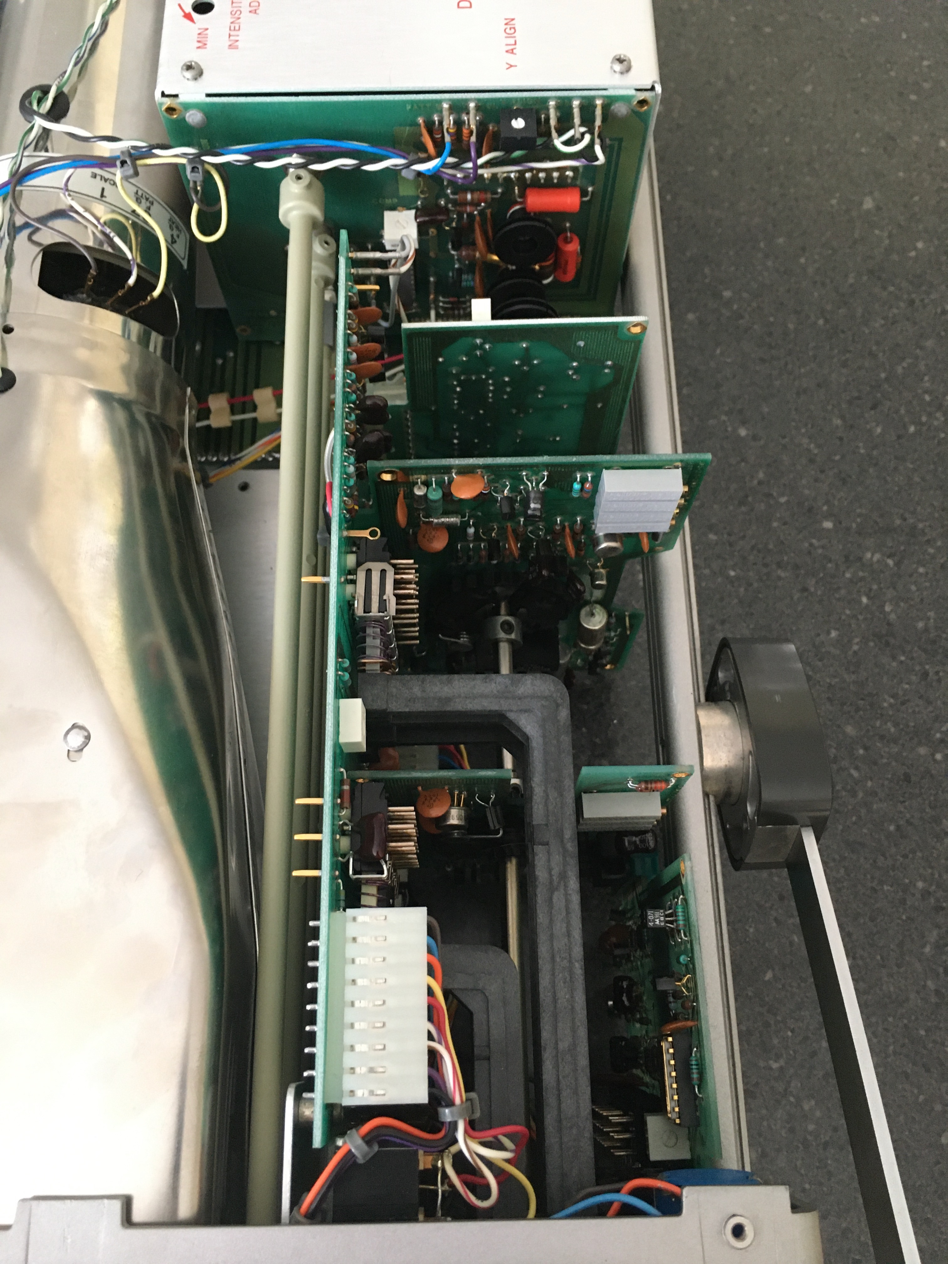
The PCB in the front is the vertical preamplifier, where a significant part of the signal processing takes place. The one in the back, as is clearly evident from the transformer, the large capacitors, and the power MOSFETs (most of which cannot be seen in this picture) is the power supply board. To the left are three vertical boards that deal with various timebase and triggering functions. The large rod clearly visible coming through the boards is the sweep rate adjustment (horizontal scale). All boards are clearly labelled on the silkscreen. The setup is ingenious and makes efficient use of limited space. It is also worth noticing that all parts are through-hole, typical of instruments of that era. This will make part replacements much more pleasant. Another important aspect is the prevalence of test points; this will make debugging much simpler when cross-referencing with the service manual.
On the other side of the scope, the CRT is visible, and its PCB lies below a cover warning of the presence of 3kV. Other PCBs are sandwiched in between these, dealing with the various other functions available. All are easily accessible; the scope is clearly meant to make servicing simple.
With the help of eevblog, I narrowed down the problem to the vertical pre-amplifier board. With some more probing, it turned out to be a leaky diode. Unfortunately, these sorts of component failures are common in 50-year-old equipment.
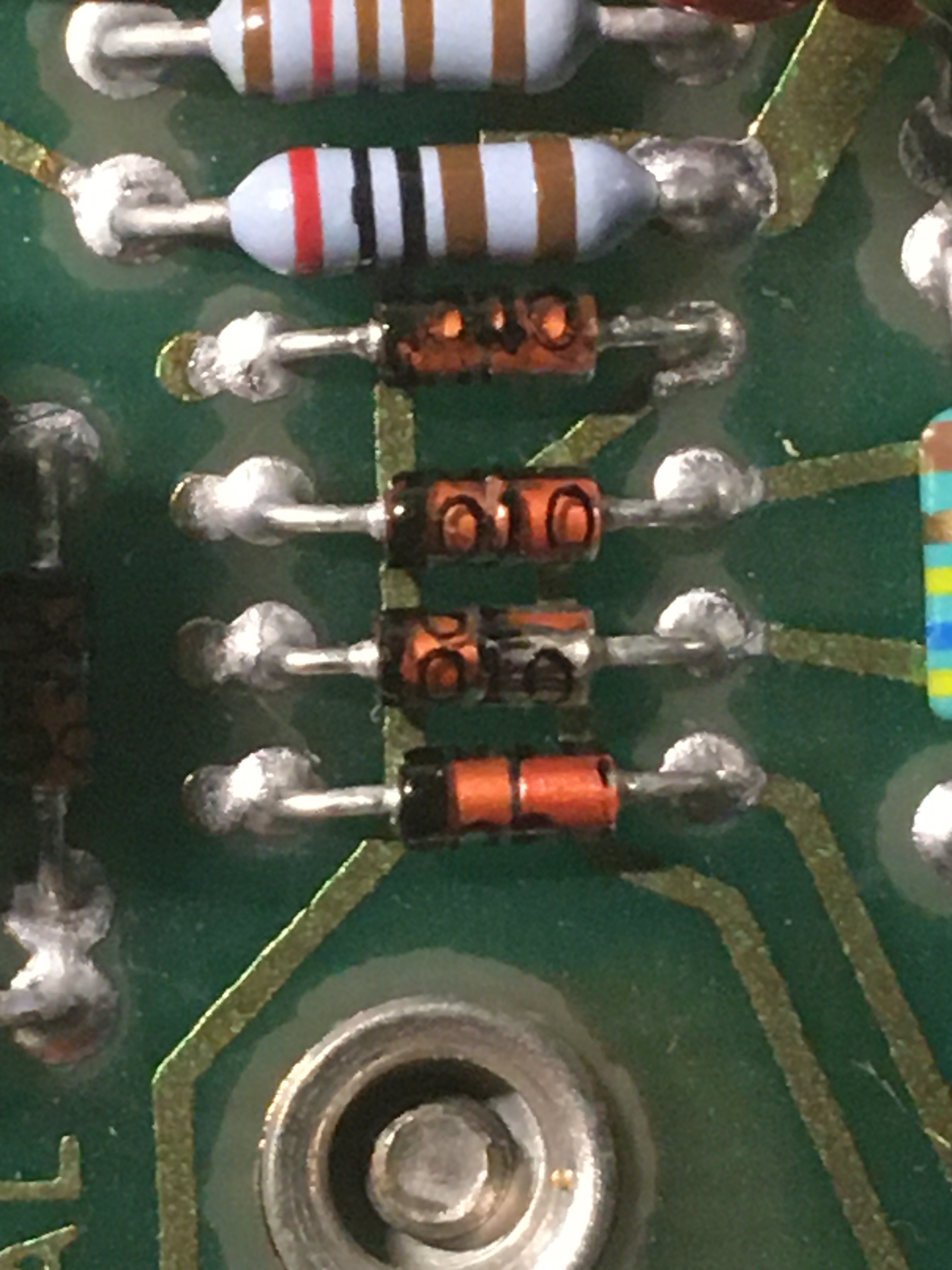
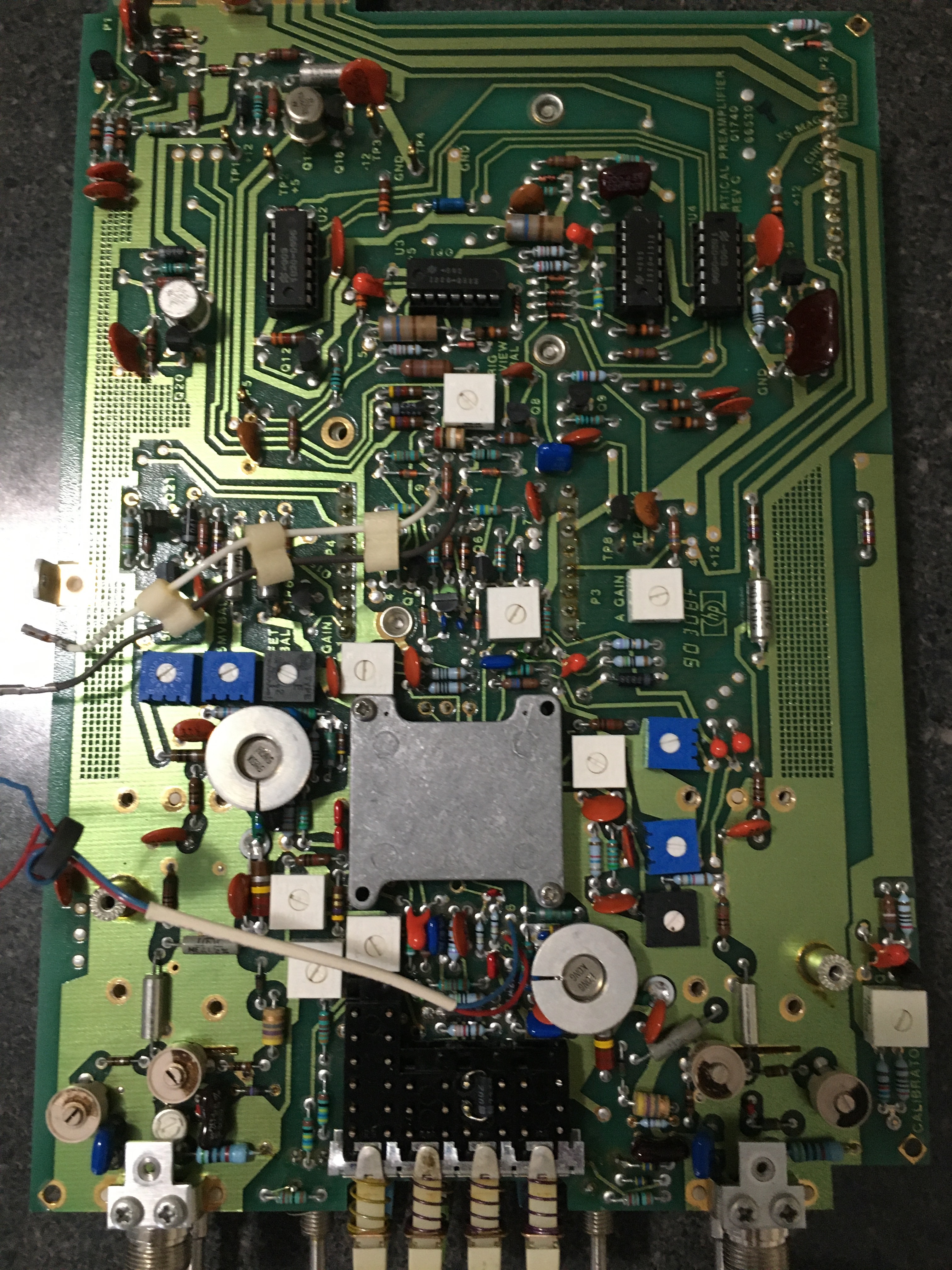
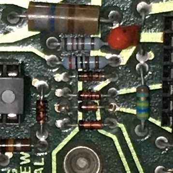
These diodes are located on the pre-amplifier board, to the right of the only horizontal 14-pin IC (lying on a vertical line striaght through the middle of the PCB). I removed this PCB, desoldered the previous diode, and replaced it with a 1N4148. In retrospect, removing the board was unnecessary, but this was my first time replacing a PCB component.
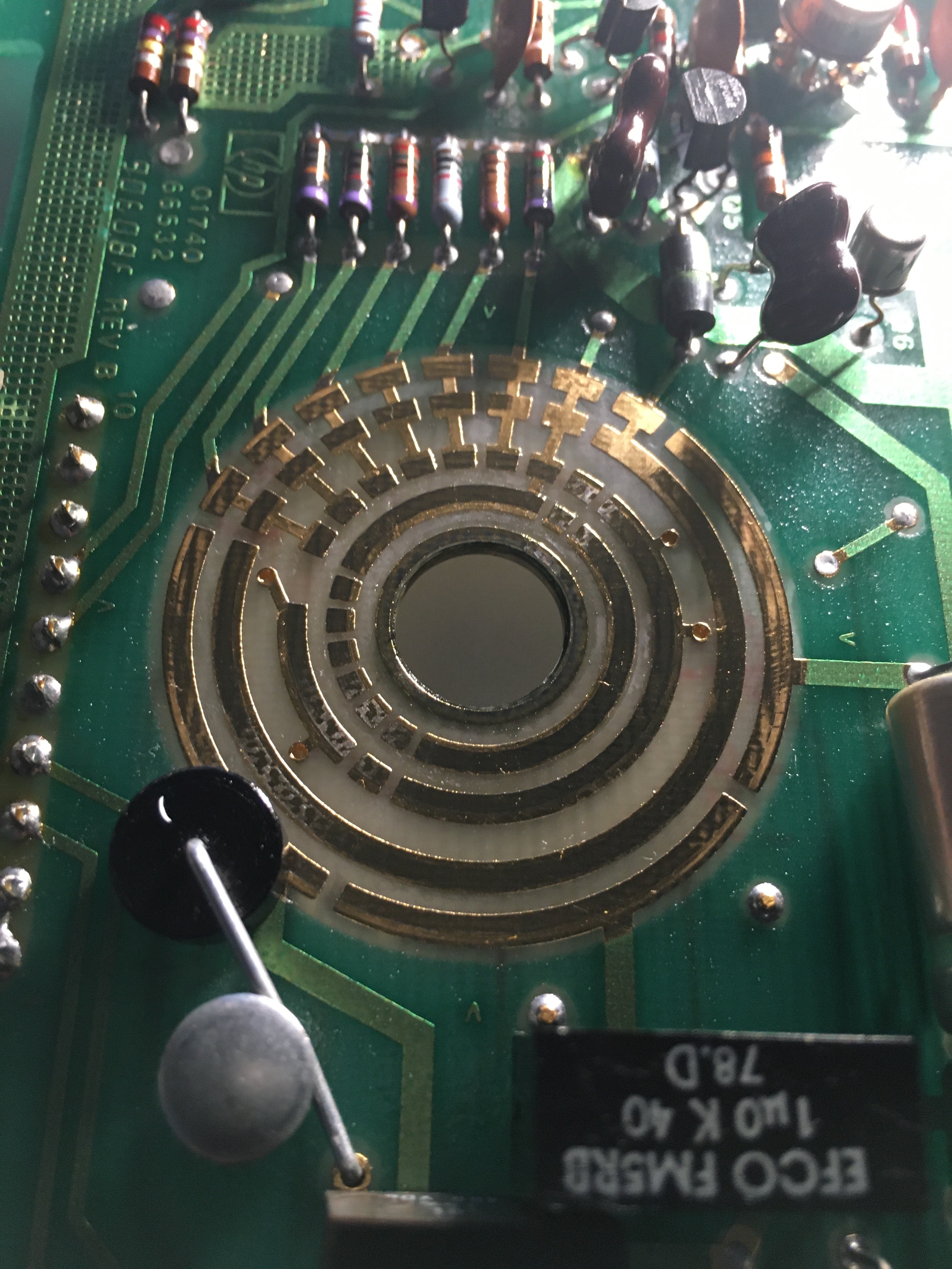
Following this replacement, the scope worked perfectly. I however did not know this at the time, and thought I had another problem which led to me cleaning the timebase adjustment rotary sitch contacts. This is always good to do regardless, especially in old equipment. Once disassembled, the gold contacts can be cleaned with a Q-tip and some IPA; some DeoxIT can also be sprayed on. New grease is then required to lubricate the contacts.
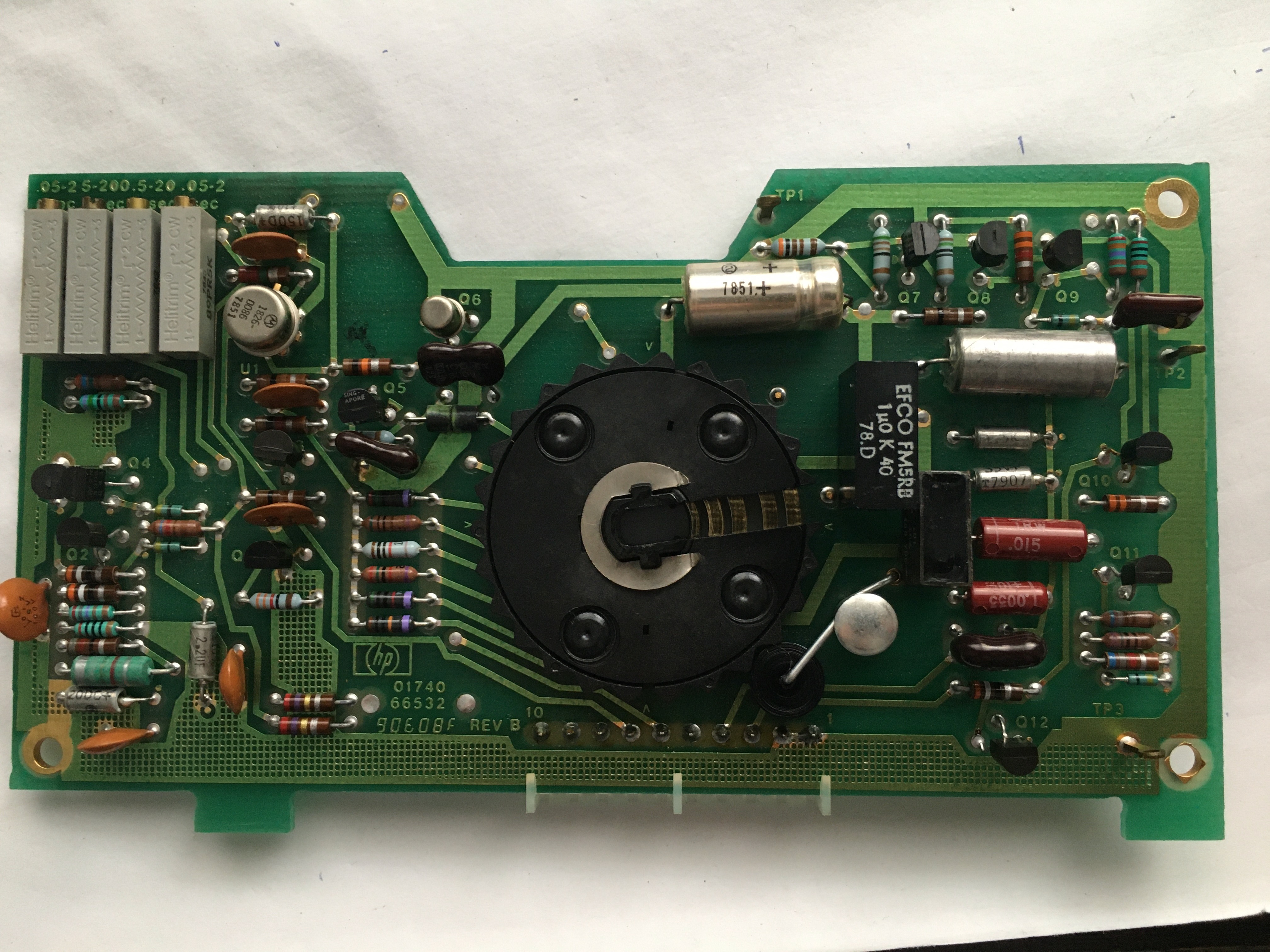
Unfortunately, while measuring some voltages with my multimeter, I slipped and shorted out a transistor on one of these timebase PCBs. No substitute part was listed in databases, and ordering a new one from Sphere proved very expensive. Instead, I replaced it with a 2N2222, and correct operation resumed.
A last issue was that the fuse holder was broken, and therefore the fuse would sometimes make contact with the chassis, arc, and blow. I repaired this with some electrical tape, but a more permanent solution will be to wire in a new fuse holder.